JACK- The Robot Dog (Quadrupedal Robot)
.png)
Introduction
This project documents the design and development of JACK, a compact, open-source quadrupedal robot dog. Conceived as a collaborative academic effort during my B.Tech at IIT Bhilai, the robot was built from scratch and underwent two major phases: initial prototyping and subsequent improvements for advanced navigation. The project aimed to explore unconventional robotics, focusing on custom mechanical design, embedded electronics, and autonomous capabilities.
Objectives
The primary motivation behind JACK was to gain hands-on experience in robotics by building a legged robot capable of basic locomotion and navigation. The objectives included:
- Designing a robust mechanical structure inspired by modern quadrupeds.
- Developing custom electronics for real-time control.
- Develop the quadruped ronot for delivery on uneven terrain.
- Experimenting with gait patterns and navigation strategies. This project also served as a platform to apply theoretical knowledge from coursework to a real-world robotics challenge.
This was a collaborative project that was executed in two different phases during my B.Tech at IIT Bhilai-
This project was executed in two phases during my undergraduate journey:
- Phase I: Design & development of the basic working prototype.
- Phase II: Improvements for better navigation and modular control.
Phase I: Prototype Development
In Phase I, we successfully built a working prototype of JACK, our quadrupedal robot, integrating custom mechanical, electronic, and control systems. I worked on the electronics and learned the design aspects while working with my senior, Santosh K. Prajapat. In this phase the legged robot was designed from scratch with some design experimentation and analytical approach.
Mechanical Design
Each leg is designed with three joints, analogous to a robotic arm, and actuated by servo motors. The mechanical frame was designed using Autodesk Fusion 360, and the legs were assembled with three servo-driven joints each, allowing for iterative design and experimentation. Apart from the leg designs, the main body was kept as a flat plate unlike the cylindrical structure seen in service robots like Unitree Go1/2.
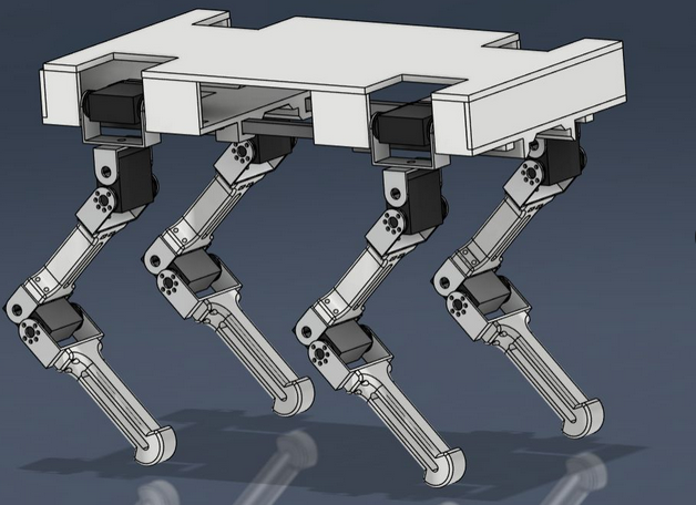 CAD Model of the Legged_Robot Phase 1 made on Autodesk Fusion 360
Electronics & Hardware
The initial phase focused on building a functional prototype from scratch. A custom RX-TX wired controller with Arduino Boards was developed on a PCB, featuring a joystick for driving the speed of body movement in any direction and buttons for directional control and to switch between gait patterns(referring to march past and the most common, trot gait; gait system was not much established in this phase). The electronics were designed to support real-time embedded control and communication with the robot’s actuators. The electronics were custom-built, featuring an Arduino-based controller and a wired joystick interface for manual operation.
.png) In-hand Controller counterpart
In-hand Controller counterpart
Kinematics & Control
The leg kinematics were modeled in MATLAB Simulink using inverse kinematics solvers. Using MATLAB Simulink allowed us to quickly iterate on the kinematic model and validate the joint trajectories before physical implementation. This enabled precise control of each leg’s movement, allowing the robot to achieve basic locomotion in three degrees of freedom (x, y, yaw) via joystick input.
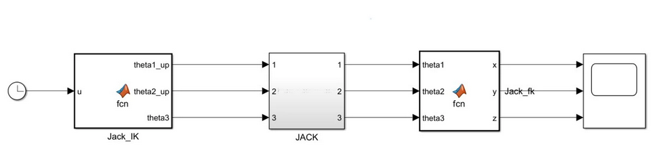 High level view of the Inverse kinematics for each leg
This robot was prepared as a part of a Robotics Fundamentals course curriculum and we reached some basic Low level embedded & MATLAB programmed stage. We first programmmed the three joints in a single Leg with the analogy of a robotic Arm with 3 servo motors. The leg kinematics was modelled with MATLAB Simulink using inverse solver.
.png) Top view of the base electronics
Top view of the base electronics
At the end of phase I, each leg of the 4-Legged Robot dog could move using continuous Inverse Kinematics to produce joint angles as per the desired trajectory point. An algorithm code was made in order to control the motion of the robot dog as per the input from a in hand Controller device. The Controller setup present onboard the Robot dog processes the input to perform the power distribution into the separate motors to locomote in a particular direction.
 Testbench setup to run tests for the leg motion and trajectory following
Testing was conducted on a custom testbench to validate leg trajectories and overall stability. The prototype successfully demonstrated basic walking, turning, and stopping maneuvers. These tests highlighted areas for mechanical reinforcement(like X-bar reinforcement, foot grippers) and software optimization(sleeps cycles, control algorithms to minimize jerks, reduction in overheating of the electronics).
Such a mechanized quadrupedal robot can be leveraged to various applications like inspection/investigation of an area. The demonstration of this 4-legged robot prototype won the first prize at the Inter-Departmental Research Meet ‘24.
Phase II: Improvements & Advanced Features
The $2^{nd}$ Phase of this project was executed with two of my batchmates- Dhananjay, Harshit and a senior, Vedhamsh Bode.
 Modified Leg configuration in Phase 2
Building on the initial prototype, the second phase focused on enhancing the robot’s capabilities and robustness and modularize the High Level Layer(ROS2 Layer). The main goals were to improve locomotion stability, introduce basic autonomous navigation, and refine the control algorithms.
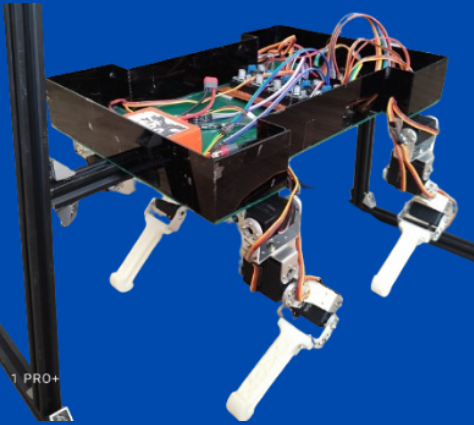
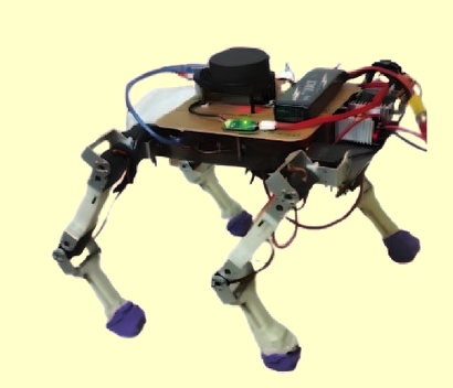 Modified Quadruped Design and body
In the second phase, the robot’s torso structure was replaced with a metallic body reinforced for durability, and additional sensors(LIDAR, IMU) were integrated for feedback. The embedded stack was upgraded with an onboard processor(Raspberry Pi) running the microcontroller to support wireless operation using remote ssh, and the software was modularized for easier experimentation. Wireless communication enabled remote control and debugging. The robot’s navigation system was enhanced to allow remote operation for now.
High-Level Control Setup
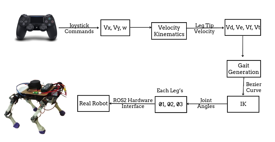 HL Architecture of the Robot Dog
Remote Debugging & Operation (via Raspberry Pi): Our quadruped robot is equipped with a Raspberry Pi 4B as its central processing unit, enabling remote access over Wi-Fi or SSH. This setup allows us to:
- Monitor sensor data in real-time.
- Deploy updates wirelessly.
- Debug motor outputs and sensor readings without physical intervention. The Pi can act as a bridge between sensor feedback and the actuation logic, ensuring that control algorithms can be tweaked and tested rapidly—particularly useful during field tests.
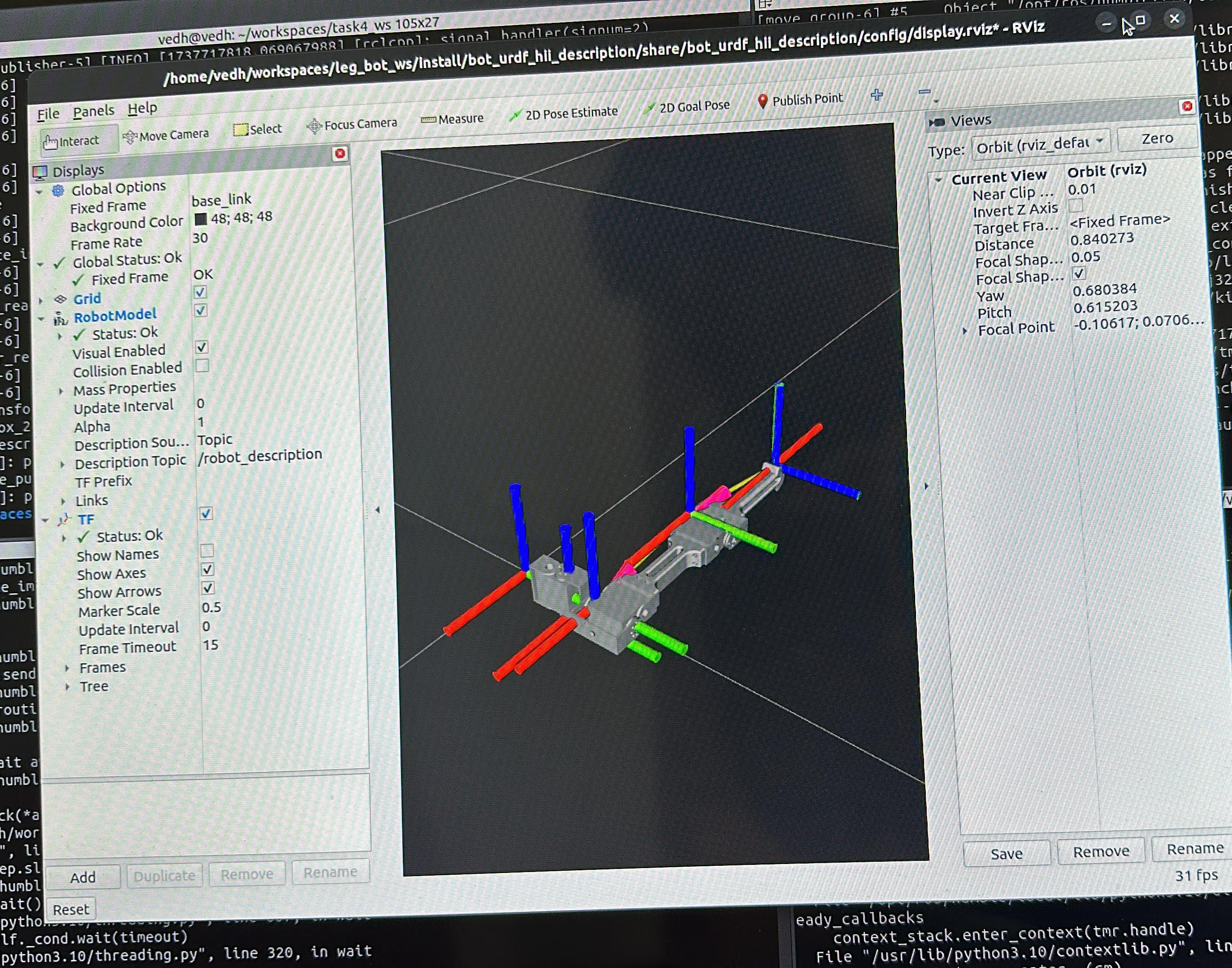
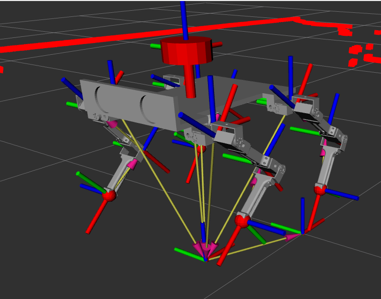 JACK TF vectors in Rviz view
Sensor Integration
IMU (BNO055): Measures orientation (roll, pitch, yaw), essential for CoG adjustment. Used to detect tilt and re-center the body by adjusting leg heights dynamically.
2D LiDAR: Generates a 2D scan of the surroundings for obstacle detection and local path planning.
Motion & Navigation
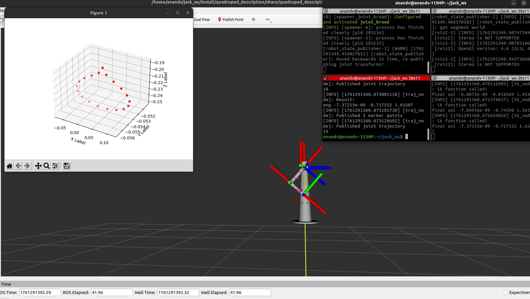
Leg Trajectory planning & Locomotion And this time we setup to the Leg testbench stand in RviZ to avoid the environmental faults and cautioning for our servos damage due to prolonged command or unconstrained valuesthat occur in hardware testing during algorithm development and testing
 Simulation Testbench in Rviz for testing foot trajectory following
For walking, two different phases are needed from the trajectory of leg foot(end-effector)- Swing phase and stance phase(the two main parts of a gait cycle for the complete sequence of a anatomy(dog)).
Stance Phase- The period when the foot is on the ground, absorbing and supporting body weight. (ts=0.6*T)
- Begins with Initial Contact with ground.
- The leg absorbs impact and then pushes the dog forward (propulsion).
- Ends with Toe-Off, the moment the foot leaves the ground.
Swing phase- The period when the foot is in the air, moving forward to prepare for the next step.(ts=0.4*T)
- Begins with Initial Swing, when the foot lifts off the ground.
- The leg moves through the air, preparing for the next contact with the ground.
 Bezier curve trajectory with 6 points(2 overlapping)
Gait Evolution: We started with a basic trot gait but observed instability due to poor body weight distribution or some dynamic constraints. The gait engine is being upgraded to support:
- Height-adaptive stride length, reducing ground impact during each step.
- Dynamic phase-shifted gaits (e.g., crawl gait with staggered leg motion).
- Stability-aware gait switching, influenced by IMU tilt data, and other techniques
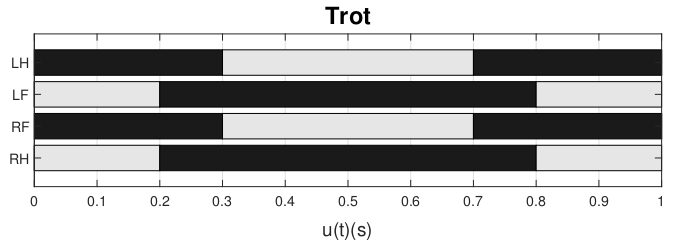 Hildebrand chart of Trot gait
Navigation Algorithms: At present, the quadruped is remotely operated. We’re making it semi-autonomous(mission based) with:
- A path planning on 2D occupancy grids generated from LiDAR data.
- Custom logic for re-routing when IMU detects instability (e.g., large roll/pitch).
- Basic waypoint tracking to move the robot along a desired path, using dead-reckoning corrected by LiDAR-based odometry.
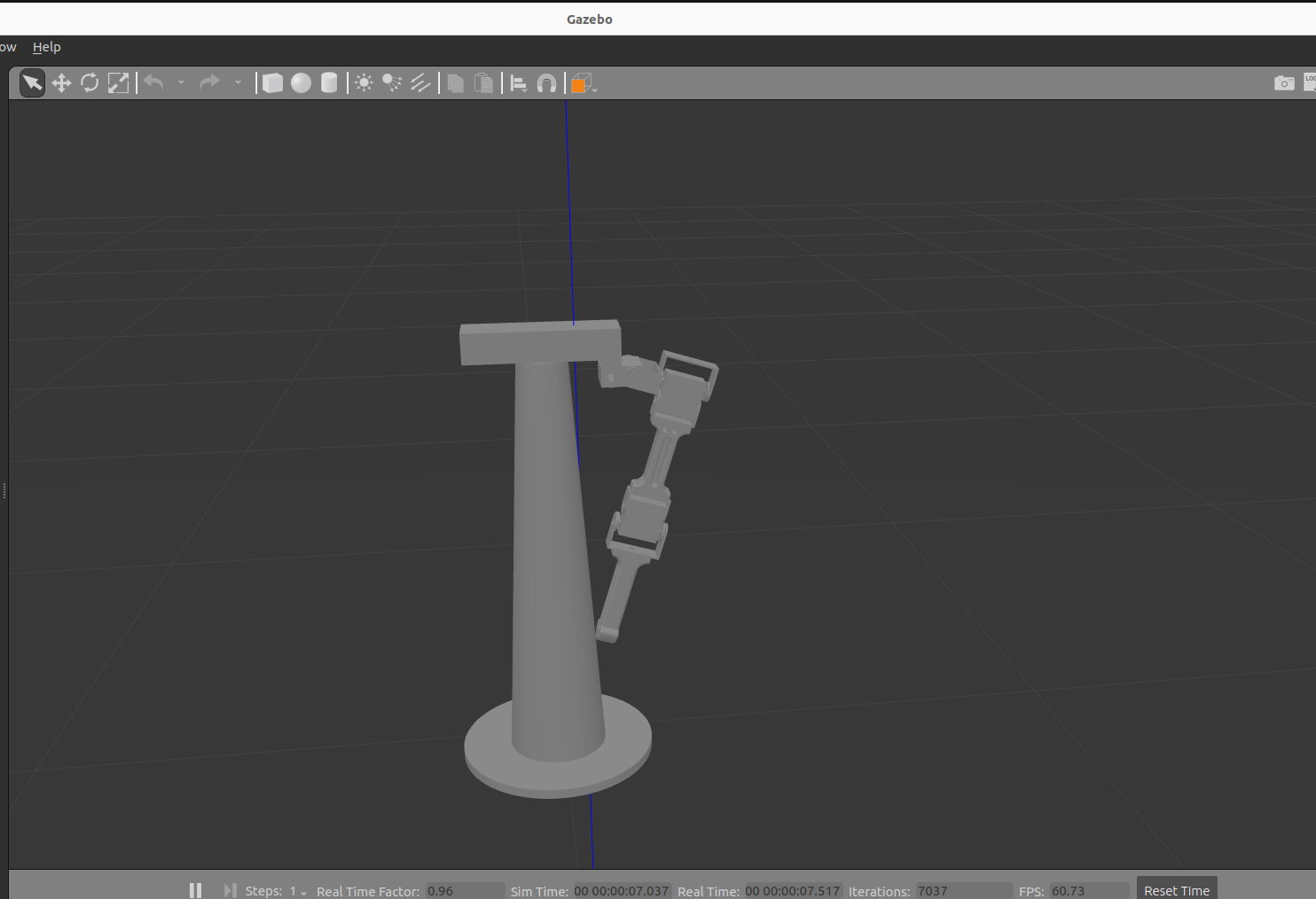
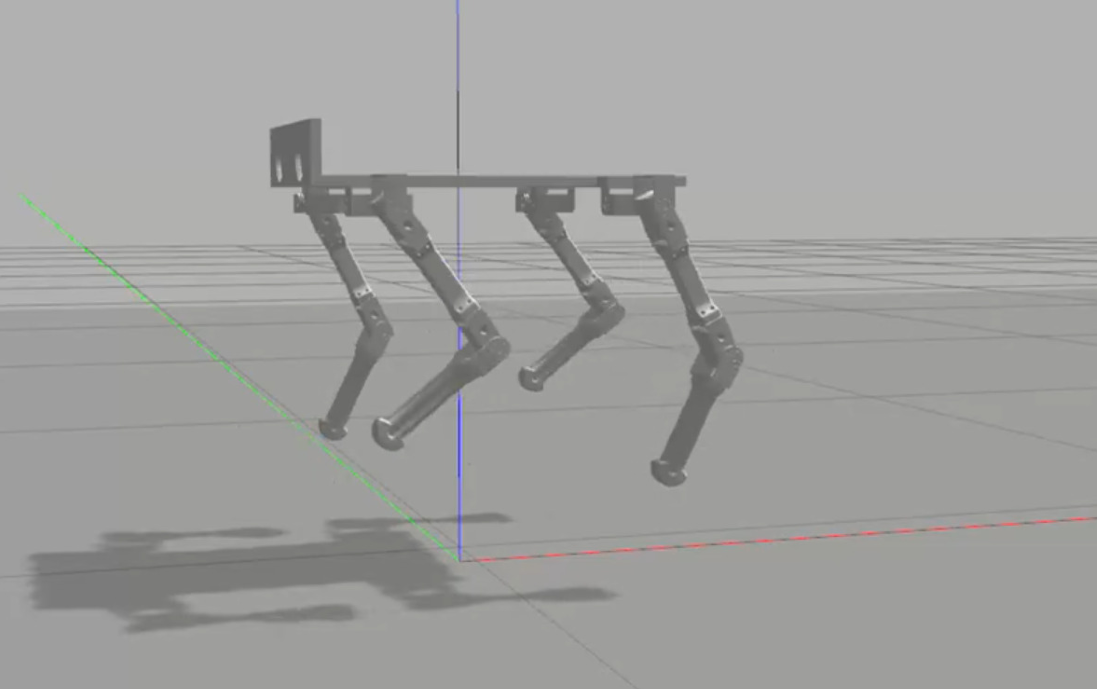 The JACK in The Gazebo Sim
Field Test Results:
Initial walking tests on tiled and moderately uneven outdoor surfaces showed:
- Reduced leg drag and fewer missed steps compared to earlier versions.
- More controllability with the onboard Kinematics solver stack and a well defined High level layer.
Challenges:
Key challenges included achieving reliable leg synchronization, managing weight distribution, and ensuring robust wireless communication. Mechanical wear and servo calibration also required ongoing attention.
The project was a hands-on experience in multidisciplinary robotics, from CAD design and embedded programming to control theory and systems & sensor integration. Iterative testing and teamwork were crucial for overcoming technical hurdles.
Future improvements
This Robotic platform can include further modification to implement semi-autonomous nature with the ability to detect and avoid obstacles in real time and advanced SLAM (Simultaneous Localization and Mapping), incorporating visual sensors, upgrading to more powerful actuators, and developing fully autonomous navigation and path planning capabilities.
The Demonstration video of the Quadruped can be found below or here
The Github Repo can be found here: Quadrupedal-Robot-Jack
Research Directions:
- Investigate Reinforcement Learning for adaptive gait control based on terrain type and using other techniques on the to-do list.
- Develop ROS2 Nav2 stack compatibility for integrating global planners.
References & Resources: