SPYDER — 12-DOF Quadruped Spider with Arduino Control and Bluetooth Telemetry
Design and embedded wireless control for a 12-DOF quadruped robot spider using Arduino, HC-05 Bluetooth UART, and an Android telemetry app.
Introduction: Sharpening the Axe Before the Swing
In the spirit of the age-old lumberjack analogy, this project wasn’t about rushing to build a robot. Instead, it was a meticulously pre-planned engineering experiment, focusing not only on functionality but on modularity, control theory, and real-time human-robot interaction.
Over the summer, I built Quad-Spider, a Bluetooth-controlled quadruped robot that responds to text-based motion commands from a custom Android application created using MIT App Inventor. This article is a deep dive into how I went from concept to prototype, and how I iterated across hardware limitations, software design, and control stability.
Mechanical and Electrical Framework
Robot Chassis & Motion
- Leg Configuration: 4 legs × 3 DOF = 12 degrees of freedom
- Servos: 12 × SG90 servo motors (PWM-controlled)
- Structure: Lightweight acrylic chassis, designed for symmetry and center-of-mass alignment
- Power Source: 11.1V 2200mAh LiPo Battery regulated via a buck converter to 5–6V for stable servo operation
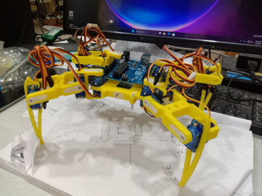 Spyder model
Pin Mapping
- Servo Control Pins: Digital Pins 2–13 (1 per servo)
- Bluetooth TX/RX: Pins 10 (RX), 11 (TX) via
SoftwareSerial - Arduino Board: Arduino Uno or Nano
Bluetooth Communication Architecture
flowchart LR
    subgraph UI["Mobile Controller"]
        A[Android MIT App] -->|Bluetooth SPP Packet| B[HC-05 Wireless Module]
    end
    subgraph MCU["Embedded Processing"]
        B -->|UART 9600 Baud| C[Arduino MCU SoftwareSerial]
        C -->|Command Parser| D[Gait State Engine]
    end
    subgraph Output["Actuation"]
        D -->|12x PWM Channels| E[12x SG90 Micro Servos]
    end
Module: HC-05 Bluetooth Serial Module
- Baud Rate: 9600
- Voltage Divider: 8kΩ & 12kΩ resistors on RX line for 5V → 3.3V compatibility
- Communication Protocol: UART serial interpreted by Arduino and parsed via custom logic
Command Structure
Simple line-based protocol:
"w 5\n" // Walk forward 5 steps
"s 1\n" // Sit once
"k 3\n" // Shake leg gesture 3 times
Each command consists of a keyword and step count, terminated with \n.
Software Stack on Arduino
Yes, you read that right… Instead of a brain for high-end compute, we decided to use this one instead.
Core Libraries
Servo.hfor PWM controlFlexiTimer2.hfor periodic timed control of all 12 servosSoftwareSerial.hfor Bluetooth handling
Servo Timing & Synchronization
FlexiTimer2used at 20ms intervals (50Hz PWM)- Smooth motion via step-by-step interpolation
- Avoided servo jitter and overloads with staggered updates
Command Parsing Logic
Dropped SerialCommand in favor of memory-efficient manual parsing:
1
2
3
4
5
6
7
8
9
if (BTSerial.available()) {
    char c = BTSerial.read();
    if (c == '\n') {
        parseCommand(buffer);
        buffer = "";
    } else {
        buffer += c;
    }
}
This allows precise one-line-at-a-time parsing with low memory overhead.
The Custom App – Built with MIT App Inventor
Features
- Clean UI with command buttons (Walk, Sit, Wave, etc.)
- Input box for custom step count
- Real-time Bluetooth response display via
.ReceiveText - Handles newline-based protocol and displays the latest status line
Workflow
- On button click: send
"cmd step\n"string - Use
.BytesAvailableToReceiveand.ReceiveText(-1) - Split at
\n, select last item from list - Display in label or debugger box
Design Thinking & Challenges
Constraint-Aware Coding
- 2KB SRAM limit on Arduino Uno
- Lean memory buffers without dynamic allocations
- Pin mapping optimized to utilize available digital outputs without conflict
Power Management
- Buck converter regulated to ~6V output
- Logic rails isolated from high-draw servo power to prevent brownouts and resets
Gesture Sequencing
- Each gait and gesture defined as target joint angle arrays
- Step interpolation applied across transitions to reduce mechanical shock
Demo & Results
Visit the GitHub repository for:
- Arduino firmware
- MIT App Inventor
.aiasource - Wiring schematics
- Kinematic calculations and gait sequence maps
Conclusion
This project demonstrates coordinated 12-DOF multi-leg actuation, wireless command parsing, and real-time mobile interfacing under resource-constrained embedded hardware.
- GitHub Repository: Spider_Quad